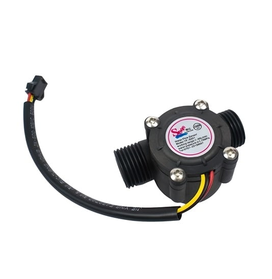


Water Flow-measurement Sensor (0.5 inch)
Product Details
Flow Measurement: The primary function of a water flow sensor is to measure the rate at which water is flowing through a pipe. It provides data in units such as liters per minute (LPM) or gallons per minute (GPM), depending on the calibration and configuration.
Pipe Size: The "half-inch" designation typically refers to the size of the pipe or tubing that the sensor is designed to be installed on. In this case, it's intended for use with pipes that have a nominal inner diameter of approximately half an inch (12.7 mm).
Working Principle: Water flow sensors use various methods to measure flow rate. Common principles include:
- Turbine: These sensors have a rotor that spins as water flows through, and the rotation speed is directly proportional to the flow rate.
- Hall Effect: Hall effect sensors detect the movement of magnets attached to a rotor inside the sensor. The output signal varies with flow rate.
- Ultrasonic: Ultrasonic sensors use sound waves to measure the velocity of water, which is then used to calculate the flow rate.
Output Signal: Water flow sensors typically provide an electrical output signal, which can be analog (e.g., voltage or current) or digital (e.g., pulses or a digital interface like RS-485). The type of signal depends on the sensor's design.
Applications: Water flow sensors are used in various applications, including:
- Residential and commercial water meters
- Monitoring water usage in industrial processes
- Irrigation systems for agriculture and landscaping
- Leak detection in plumbing systems
- Environmental monitoring and research


