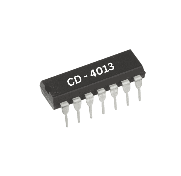

CD4013 Counter IC
Product Details
Dual D-Type Flip-Flop: The CD4013 contains two identical D-type flip-flops, often referred to as FF1 and FF2. Each flip-flop can store a single binary bit (0 or 1).
Clock Inputs: Each flip-flop has an independent clock input (usually labeled as CLK or CLOCK). Data at the D input is transferred to the Q output when the clock input transitions (rising or falling edge, depending on the configuration) from low to high.
Data Inputs (D): Each flip-flop has a D input that allows you to input the data you want to store in the flip-flop.
Set (S) and Reset (R) Inputs: The CD4013 also includes Set and Reset inputs (often labeled as SET and RESET or S and R). These inputs allow you to set or reset the flip-flop outputs to specific states, overriding the data input.
Flip-Flop Pairing: The CD4013 is often used in pairs. In this configuration, one flip-flop can serve as a data latch, while the other can be used as a storage element for a counter or shift register.
Clock Edge Sensitivity: The CD4013 flip-flops can be configured to respond to either the rising or falling edge of the clock signal, depending on how they are connected.
Power Supply Voltage: The CD4013 typically operates with a power supply voltage in the range of 3 volts to 15 volts, making it compatible with various digital systems.
Applications: The CD4013 is used in a wide range of applications, including sequential logic circuits, data storage, data latching, flip-flop toggling, and more.


