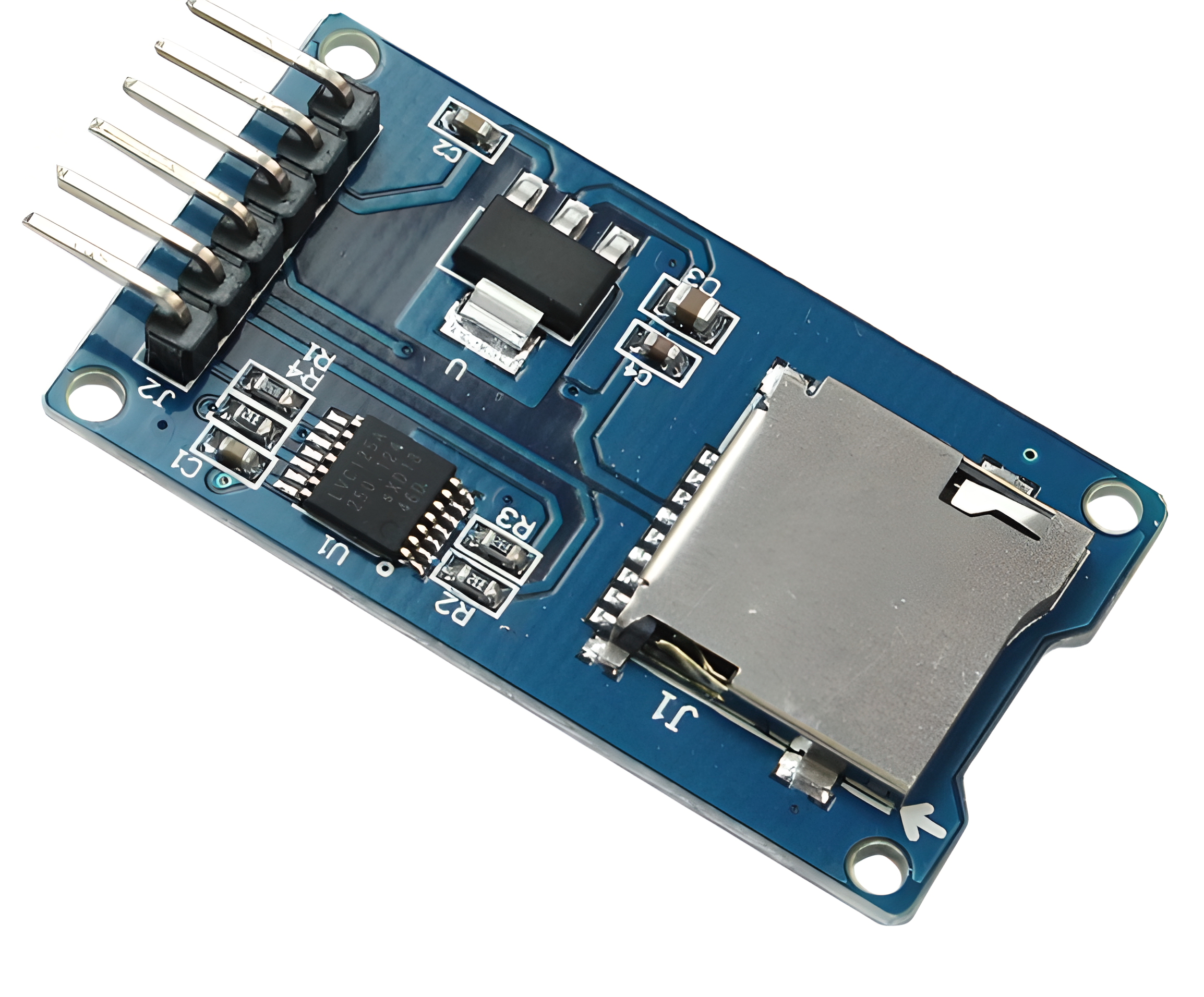


Micro SD Card Adapter module
A Micro SD Card Adapter module is an electronic device that allows a microSD card (Micro Secure Digital Card) to be easily interfaced with other electronics, such as microcontrollers, development boards, or other devices that use SD card storage. This module simplifies the process of reading and writing data to a microSD card, making it a common component in projects that require data storage.
Here are the typical features and components you might find in a Micro SD Card Adapter module:
1. MicroSD Card Slot: This is the slot where you insert the microSD card. The module usually provides a secure and easy-to-use mechanism for inserting and removing the card.
2. SPI Interface: Most Micro SD Card Adapter modules communicate with microcontrollers or other devices using the Serial Peripheral Interface (SPI) protocol. SPI is a common communication protocol that allows devices to exchange data.
Non-returnable
SKU - R-0470
Rs.60.00
Share:
Product Details
3. Voltage Level Conversion: MicroSD cards typically operate at 3.3V logic levels, while some microcontrollers or development boards might use 5V logic levels. The module might include voltage level converters to ensure proper communication between the microcontroller and the microSD card.
4. Chip Select (CS) Pin: The module will have a pin that the microcontroller uses to select the microSD card for communication. This pin is often referred to as the Chip Select (CS) or Slave Select (SS) pin.
5. Power Supply Connections: The module usually requires a power supply connection, typically 3.3V or 5V, depending on the microcontroller's voltage levels.
6. Data Transfer LEDs: Some modules include LEDs that indicate when data is being transferred to or from the microSD card. These LEDs can be helpful for debugging and monitoring activity.
7. Level Shifters: If the module supports different voltage levels (e.g., 3.3V microcontroller and 5V microSD card), level shifters might be present to convert the voltage levels between devices.
8. Logic-Level Conversion: Logic-level shifters might be used to ensure that the signals between the microcontroller and microSD card are correctly interpreted at both ends.
9. Pull-Up/Pull-Down Resistors: These resistors help maintain stable signal levels during communication.
10. Mounting Holes or Header Pins: The module might include mounting holes or header pins for easy integration into projects or breadboard setups.
Micro SD Card Adapter modules are commonly used in various projects that require data logging, data storage, or configuration settings to be saved externally. They are especially popular in projects involving Arduino and other microcontroller platforms.
When using a Micro SD Card Adapter module, make sure to refer to the manufacturer's documentation or datasheet to understand the pinout, communication protocols, and power requirements for proper integration into your project.